Denon PMA-2000IVR Operations Instructions
Browse online or download Operations Instructions for Audio amplifiers Denon PMA-2000IVR. Denon PMA-2000IVR Operating instructions User Manual
- Page / 19
- Table of contents
- BOOKMARKS
- PMA-ZOOOIVR 1
- Read Instriclions . 3
- __ _13 4
- ‘I6 ~/Oht’nS 7
- .-...______. -~ 8
- SySiW7S 9
- E : I'zlllSc: 11
- : Auto soarcl1 11
- ..rv or VCR near the 12
- IYIV/I 2 13
- Tolepl~orw (03) 3837-53~1 14
- 852,.2!j’f 15
Summary of Contents
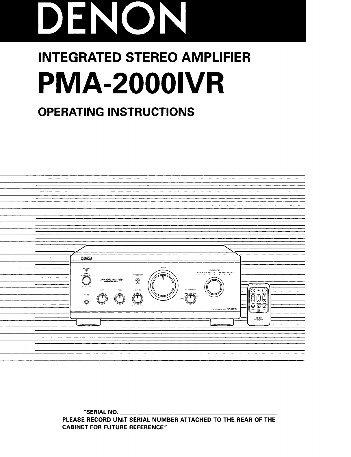
INTEGRATED STEREO AMPLIFIER PMA-ZOOOIVR OPERATING INSTRUCTIONS “SERIAL NO. PLEASE RECORD UNIT SERIAL NUMBER ATTACHED TO THE REAR OF THE CA
The accessory Remote Control Unij: is used to conl’ral the amplifier fr-om a convenient distance. I. Remove the battery cover on th
-. .-... - .__I__-.-... c -. _... .._ -..-.-___.-..-.-. Use these to co~rtrol the CD player connected to the PMWOO01VR. : Playback : stop E
IF the set does not seern to be operating properly, check the points listed below. If these points do not apply, the set rnay b
(8 G/ohms Load) 80 w + 80 w 20 HZ i0 20 kl-lz, -i-.1-I.D. 0.07 % (4 G/ohms Load) 16OW+ .lFjOW rJlN, I ki-lz, T.1H.D. 0.7 % ‘I 50 nlV ~~~S
‘I 6-I 1, YUSWIMA 3-CHOME, EWNKYOIJ--KCI, TOKYO 113-0034, JAPAN Tolepl~orw (03) 3837-53~1 Prmted iri Japan 51 1 3917 001
Audio Products Australia Pty Ltd. 67 O’Riordan Street, Alexandria NSW 2015, Australia Tel: (02) 9669-3477 Fax: (02) 9578 -0140 Digita
.-,--_ -..“” ,, “,, ,,-- “, U~~~.~~ NAME -__ ,, ,~ ,“,_---~ -“--ll__.“-_ ----_._ ^“, “---~ IXALER ADDRES:i I I l.,--.-.” .-.~. .,... .-..--.^-I- -
- ! I
-Y The lightning flash with arrowhead symbol, within an equilateral triangle, is intended to alert the user to tho presence ot unins
1. 2. 3. 4. 5. 6. 7. 8. 9. 1 0 1 I 12. Read Instriclions .- All Lhe safety and operating inslructiolI.5 should be read before the product
1. Always keep the POWER switch on the main unit turned on. 2. Turn the power on and off from the remote control unit. 3. Unplug t
r ~~~~~~ 1 When Ihe power switch is tur,ned ON (-1, the MUTE/STANDBY LED lights. When .llie power swil is turned ON, power is supplie
A I-- L. I 1 These are input terminals ,for CD players, iurntables, &l/FM tuners, tape decks or other playback components. - ._.__
Connect the turntable’s ground wire here is terminal is used to reduce noiso when a xtable, etc., is connected. lees not provide gro
--. 8 ot plug in The power cord until all connections at-c e to connect ‘rho leii and righe channels properly. the plugs securely. I
* Make sure that all the connections are proper by referring to the rear panel. a Check the polarity (positive and negative) of c
More documents for Audio amplifiers Denon PMA-2000IVR

Related products and manuals for Audio amplifiers Denon PMA-2000IVR
 (6 pages)
 (2 pages)
 (4 pages)
 (4 pages)
 (2 pages)
© 2020, manymanuals.com. All rights reserved. | 0.417 s |
 Manymanuals.com
 Manymanuals.de
 Manymanuals.fr
 Manymanuals.it
 Manymanuals.pl
 Manymanuals.cz
 Manymanuals.es
 Manymanuals-pt.com
Comments to this Manuals