Connections Fader Start
ENGLISH
Specifications
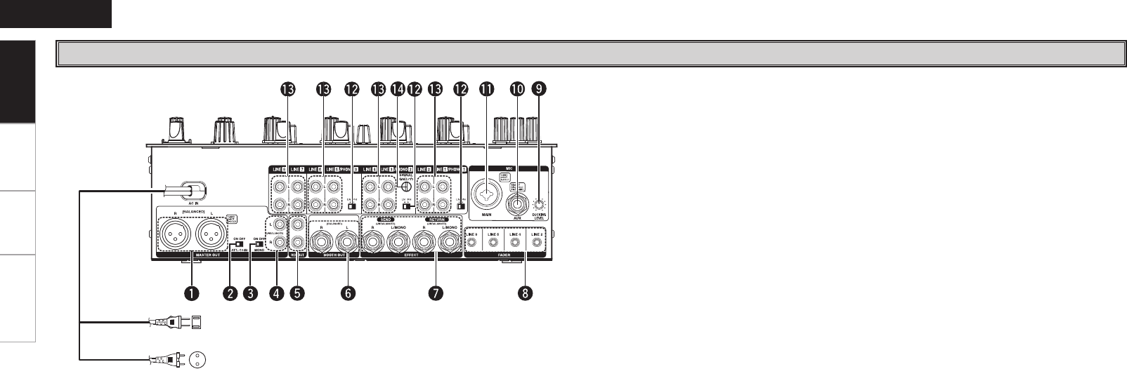
Rear Panel
q MAIN OUT (BALANCED) connectors
• These XLR type connectors provide a balanced
line level output.
• Connect these connectors to the balanced
analog input connectors on an amplifier or
console.
• Pin layout: 1. GND, 2. Hot, 3. Cold
• Applicable connector: Cannon XLR-3-31 or
equivalent.
w LEVEL ATT (Master out level attenuator)
• Use this to attenuate the MASTER output level
(–10 dB).
• Reference is 0 dB.
e MASTER MONO OUT ON/OFF switch
When this switch is on, mixed L and R signal is
outputted from the MASTER OUT.
r MAIN OUT (UNBALANCED) terminals
• This stereo pair of RCA terminals provides a
unbalanced line level output.
• Connect these terminals to the unbalanced
analog input terminals on an amplifier or
console.
t REC OUT terminals
• This stereo pair of RCA terminals provides a
line level output. The signal is unaffected by the
Master Level control.
• It is intended for use with a tape recorder, but is
not restricted to that purpose.
y BOOTH OUT (BALANCED) connectors
• These 1/4” TRS type connectors provide a
balanced line level output with independent front
panel Zone Level controls and are not affected
by the Master Level control.
• Connect these connectors to the balanced
analog input connectors on an amplifier or
console.
• Pin layout: Tip: Hot, Ring: Cold, Sleeve: GND
• Applicable connector: Cannon XLR-3-31 or
equivalent.
u SEND/RETURN terminals
• These 1/4” TS mono terminals allow external
processing of the program signal.
• When connect monaural type effect processor,
use Lch input and output.
i LINE 2, 4, 6, 8 FADER output terminals
Connect these terminals to the Fader input
terminals of the DN-S1200, DN-S3500, DN-
HS5500 and etc using the 3.5 mm stereo mini
cord.
o DUCKING ATTENUATION LEVEL control
DUCKING attenuation level can be adjusted.
(– ∞ ~ –20 dB)
Q0 AUX MIC input terminal
Accepts a balanced microphone with 1/4”
terminals.
Q1 MAIN MIC input terminal
• Neutric combo terminal.
• Accepts either a balanced microphone with an
XLR connector or a balanced microphone with
1/4” TRS balanced terminals.
Q2 PHONO 1, 2, 3 /LINE 1, 3, 5 switches
• These switches change the Input from Phono to
Line level inputs.
• These switches set Line level inputs when
Turntable is not connected.
Q3 PHONO 1, 2, 3 /LINE 1, 2, 3, 4, 5, 6, 7, 8 input
terminals
These stereo pairs of unbalanced RCA terminals
are Inputs for any line level device.
Q4 Phono Ground screws
This screws provide a place to connect the
ground wire from a turntable.
This terminal is exclusively for a turntable
grounding and not a safety earth ground.
Getting Started
Power cord
European models:
To power outlet (AC 230 V, 50 Hz)
U.S.A. and Canada models:
To power outlet (AC 120 V, 60 Hz)
 (7 pages)

 (26 pages)
 (1 pages)
 Manymanuals.com
 Manymanuals.de
 Manymanuals.fr
 Manymanuals.it
 Manymanuals.pl
 Manymanuals.cz
 Manymanuals.es
 Manymanuals-pt.com
Comments to this Manuals