4
ENGLISH
– TABLE OF CONTENTS –
z
Main features ..................................................................4
x
Installation .......................................................................4
c
Part names and functions ...........................................4, 5
v
Connections.....................................................................6
b
Fader start .......................................................................7
n
X-effect ............................................................................8
m
Replacing the crossfader.................................................9
,
Specifications ..................................................................9
• ACCESSORIES
Please check to make sure the following items are included with the main unit in the carton:
q Operating instructions ....................................................1 w Connection cords (3.5 mm stereo mini cord) ..................2
1
MAIN FEATURES
CONGRATULATIONS! You have purchased the DENON
DN-X800 DJ mixer from DENON.
1. X-Effect
The X-Effect is a unique feature which is designed to work
with the DENON DN-2100F and DN-2600F CD players.
The fader start of the below functions can be used with the
Crossfader.
Sampler, Hot start brake/platter, Hot start 1, 2 (each drive).
2. CH. Fader and Crossfader start
The CD player can be started or stopped simply by
increasing or decreasing the level of the CH fader or by
using the cross fader left to right or right to left. (This
function can only be used when the DENON CD players
DN-1800F, DN-2100F or DN-2600F is connected to the
DN-X800.)
3. Digital outputs
The DN-X800 allows you to record directly to CD-R,
MiniDisc or a hard disk device through it’s exclusive coaxial
digital outputs.
The digital outputs maintains a constant 16 bit / 44.1 kHz
signal.
4. Digital inputs
The DN-X800 accepts up to 4 digital inputs.
Such as our family of performers, DN-1800F, DN-2100F
,
DN-2600F, DP-DJ151 or any device with a digital output.
The sampling frequency range can be 32 kHz, 44.1 kHz or
48 kHz.
5. Enhanced input/output terminals (Analog)
8 Line, 3 Phono, 2 microphone systems, 2 Main outputs,
Zone output, Booth output, Sub woofer output and tape
output are provided independently. Effect in/out terminals
are also provided for a external effects processor.
6. 3-Band equalizer/Gain
Bass, Mid, Treble and Gain controls are available on every
input channel.
7. Crossfader contour
This feature allows adjusting the “shape” of the Crossfader
response from a gentle curve for smooth, long running
fades, to the steep pitch required for top performance cut
and scratch effects.
8. Mic post
This feature will pass the Main Mic signal into the Zone,
Booth, Tape output and Digital output signal path.
In the OFF mode, the MIC signal will not be routed through
the above outputs.
2
INSTALLATION
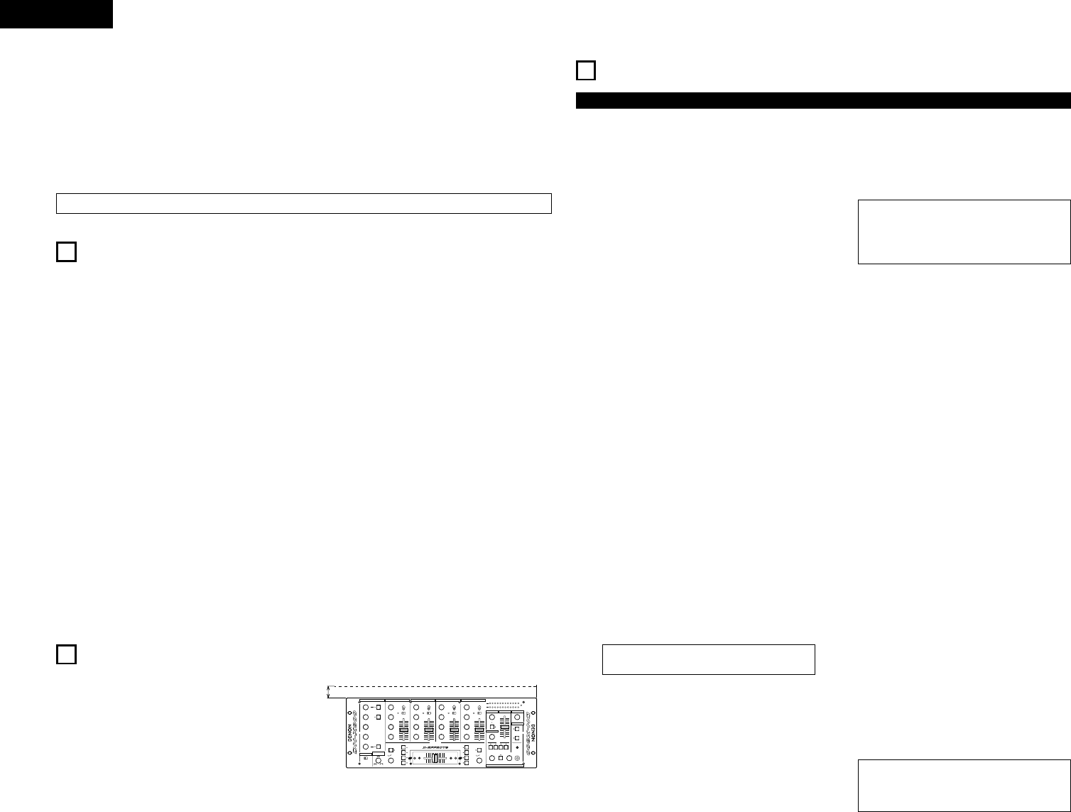
When the DN-X800 is mounted inside a coffin or DJ booth, we
recommend leaving a 3 cm blank space above the mixer if
possible.
3
PART NAMES AND FUNCTIONS
(1) Front Panel
q MIC EQ controls
• Contour the frequency response of the Main Mic input
-12 dB to +12 dB.
HI
• Adjusts high-tone microphone sound -12 dB to
+12 dB.
At the center position, sound is flat.
MID
• Adjusts mid-tone microphone sound -12 dB to +12 dB.
At the center position, sound is flat.
LOW
• Adjusts low-tone microphone sound -12 dB to +12 dB.
At the center position, sound is flat.
w MAIN MIC level control
• Adjusts the level of the Main Mic input.
e MAIN MIC ON/OFF button
• Puts the Main Mic signal into the Main outputs signal
path.
• When the button is pressed, the Main Mic is on and
the adjacent orange indicator lights.
r MIC POST ON/OFF button
• Puts the Main Mic signal into the Zone, Booth Tape
and Digital out signal path.
• When the button is pressed, the adjacent green
indicator lights.
t AUX MIC level control
• Adjusts the level of the Aux Mic input.
y AUX MIC ON/OFF button
• Puts the Aux Mic signal into the mixer signal path.
• When the button is pressed, the Aux Mic is on and the
adjacent orange indicator lights.
u Source EQ controls
• Contour the frequency response of the selected
inputs.
HI
•
Adjusts the high-tone sound -26 dB to +10 dB.
At the center position, sound is flat.
MID
• Adjusts the mid-tone sound -26 dB to +10 dB.
At the center position, sound is flat.
LOW
• Adjusts the low-tone sound -26 dB to +10 dB.
At the center position, sound is flat.
NOTE:
Clipping may occur if adjustments are set to harsh.
i GAIN level control
• Adjusts the level of the selected input 0 to +10 dB.
o Source input select switch
• Selects either a Phono/Line or Line input for the
source.
!0 LINE/DIGITAL input select switch
• Selects either a Line (analog) or Digital Input for the
Source.
• The adjacent green indicator flashes when the digital
signal is unlocked and remains lit when the digital
signal is locked.
NOTE:
You must first set the pitch slider to zero % of the
digital output source (CD, MD) before it's power is
turned on. If the green digital indicator is flashing on
the mixer, please perform the above steps.
!1 Source input fader (Ch. fader)
• Controls the level of the selected Input.
!2 ZONE level control
• Adjusts the level of the Zone outputs.
!3 ZONE METER button
• When this button is pressed down and held, the meter
indicates the stereo level in the LEFT and RIGHT
meter output. The adjacent green indicator lights.
!4 BOOTH LEVEL control
• Adjusts the level of the Booth outputs.
!5 MASTER LEVEL fader
• Adjusts the level of the Main outputs. Signals from the
channels selected with the Assign switches will be
output using the Source input fader (Ch. fader) and the
Crossfader, while signals from other channels will be
outputs using the Source input fader (Ch. fader).
!6 Peak dB CUE/PROGRAM meter
• Displays the output level following Master Level
adjustment, the peak level is held for 1 second.
Display range : -20 dB to +8 dB.
• Can switch between two display mode. See below
@3.
!7 SUBWOOFER frequency control
• Adjusts the cut off frequency of the low pass filter 40
Hz to 200 Hz.
• The low adjustment, will effect the Subwoofer output.
!8 EFFECT LOOP MAIN button
• Routes the Main signal through the external processor
attached to the EFFECT connectors on the rear.
• When the button is pressed in, the adjacent orange
indicator lights. (When the processor isn't
attached,indicator blinks.)
!9 EFFECT LOOP MIC button
• Routes the Main Mic signal through the external
processor attached to the EFFECT connectors on the
rear.
• When the button is pressed in, the adjacent orange
indicator lights. (When the processor isn't
attached,indicator blinks.)
NOTE:
When the Effect Loop Main and Mic are on, the
signal of Mic is output to all the outputs regardless
of setting the Main Mic and the Post Mic.
FREQ.
SAMP.
SAMP.
 (22 pages)
 Manymanuals.com
 Manymanuals.de
 Manymanuals.fr
 Manymanuals.it
 Manymanuals.pl
 Manymanuals.cz
 Manymanuals.es
 Manymanuals-pt.com
Comments to this Manuals