Denon AVR-985 User Manual
Browse online or download User Manual for Receivers and Amplifiers Denon AVR-985. Denon AVR-985 User Manual
- Page / 100
- Table of contents
- TROUBLESHOOTING
- BOOKMARKS
- AVR-2805/985 1
- CAUTION: 2
- ATTENTION 2
- WARNING: 2
- SAFETY INSTRUCTIONS 3
- TABLE OF CONTENTS 4
- BEFORE USING 4
- CAUTIONS ON INSTALLATION 4
- CAUTIONS ON HANDLING 5
- FEATURES 5
- CONNECTIONS 6
- (S-Video jack) 9
- (Color Diffrence Video jack) 9
- (Video jack) (Video jack) 9
- R VIDEO OUTL 12
- S-VIDEO OUT 12
- Speaker system connections 13
- Protector circuit 14
- Note on speaker impedance 14
- PART NAMES AND FUNCTIONS 15
- Remote control unit 17
- SETTING UP THE SYSTEM 18
- Auto Set/RoomEQ 20
- *System Setup 20
- Auto setup/Room EQ 21
- 1-1 Setting the Auto Setup 22
- About automatic retry 23
- About the error message 23
- (Remote control unit) 24
- 1-3 Setting the Room EQ Setup 26
- 1-4 Setting the Direct Mode 27
- 1-6 Check the EQ parameter 28
- Setting the Speaker Setup 29
- Setting the type of speakers 30
- Setting the Delay Time 31
- Setting the Channel Level 32
- FL C FR SR SBR SBL SL SW 33
- Input Setup 36
- COMPONENT 39
- Svideo Video 39
- Auto Tuner Presets 40
- Setting the Advanced Playback 41
- 4-1 Setting the Audio Delay 41
- Setting the Option Setup 42
- Setting the Trigger Out Setup 44
- 5-5 Setting the Muting Level 45
- 5-7 Protecting the setting 46
- After completing system setup 47
- REMOTE CONTROL UNIT 48
- Preset memory 50
- 6,7 : Manual search 52
- 2 : Stop 52
- 3 : Pause 52
- Learning function 53
- System call 54
- Punch Through 55
- Resetting 56
- ON / STANDBY 58
- Playing the input source 59
- MASTER VOLUME 60
- (Main unit) 62
- After starting playback 63
- ZONE 2 / 64
- REC SELECT 64
- MAIN ZONE 7.1-channel systems 65
- MAIN ZONE 5.1-channel systems 66
- SURROUND 68
- Dolby Pro Logic 69
- DTS NEO:6 mode 71
- 4, 5 2, 6 72
- Checking the input signal 73
- DSP SURROUND SIMULATION 76
- DSP surround simulation 77
- Tone control setting 79
- Room EQ OFF 80
- *Surr Parameter 80
- Bass : 0dB 80
- *Tone Control 80
- Surround parameters r 81
- Surround modes and parameters 81
- LISTENING TO THE RADIO 83
- Checking the preset stations 84
- LAST FUNCTION MEMORY 85
- TROUBLESHOOTING 86
- ADDITIONAL INFORMATION 87
- Surround back speakers 88
- Speaker setting examples 89
- Surround 90
- DTS Digital Surround 91
- DTS-ES Extended Surround 92
- DTS 96/24 93
- AL24 Processing 93
- INPUT MODE settings 97
- SPECIFICATIONS 98
- Printed in Japan 511 4172 007 100
- Telephone: (03) 3837-5321 100
Summary of Contents
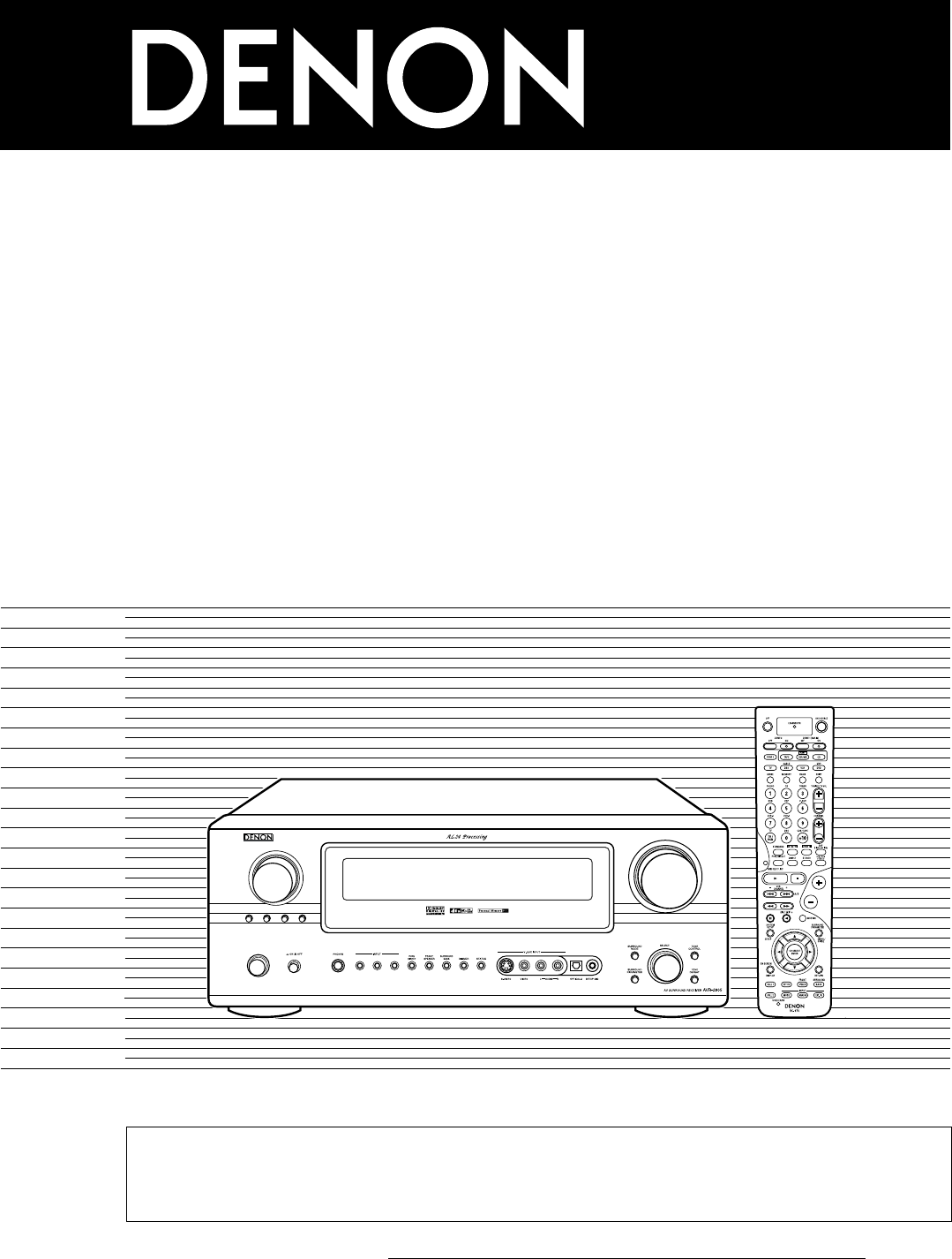
MODE ANALOG EXT. INZONE 2 / REC SELECTSOURCE VIDEOSELECTTUNINGPRESETON / STANDBYMASTER VOLUMEFUNCTIONAV SURROUND RECEIVERAVR-2805/985OPERATING INSTRUC
10Connecting the antenna terminals1423DIRECTION OF BROADCASTING STATION75 Ω/ohms COAXIAL CABLEFM ANTENNAFM INDOORANTENNA(Supplied)AM LOOPANTENNA(Suppl
Printed in Japan 511 4172 00716-11, YUSHIMA 3-CHOME, BUNKYO-KU, TOKYO 113-0034, JAPANTelephone: (03) 3837-5321
LR++OUTPUTINPUTAUX OUTBCONTROL terminalPerform the following operation before using an external controller connected to the RS--232C terminal:1. Press
12Connecting the video component equipped with V. AUX jacksTo connect the video signal, connect using a 75 Ω/ohms video signal cable cord.MASTER VOLUM
13 (L) (R) (L) (R) (L) (R) (L) (R)Speaker system connections• Connect the speaker terminals with the speakers making sure that likepolarities are m
14• This unit is equipped with a high-speed protection circuit. The purpose of this circuit is to protect the speakers undercircumstances such as when
156PART NAMES AND FUNCTIONSFront Panel• For details on the functions of these parts, refer to the pages given in parentheses ( ).eryituo!0qw!1!2!5!3!4
16Displayertyuio!0!1!2!3!4qwqINPUT SIGNAL indicatorThe respective indicator will light corresponding to the inputsignal.wINPUT SIGNAL CHANNEL indicato
17Remote control unit• For details on the functions of these parts, refer to the pages given in parentheses ( ).Power buttons ...
187SETTING UP THE SYSTEM• Once all connections with other AV components have been completed as described in “CONNECTIONS” (see pages 6 to 14), make th
193Digital InAssignmentThis assigns the digital input jacks for the different inputsources.InputsourceDigitalInputsCD DVD VDPTVDBS V. AUX VCR-1 VCR-2C
22SAFETY PRECAUTIONSCAUTIONRISK OF ELECTRIC SHOCKDO NOT OPENCAUTION:TO REDUCE THE RISK OF ELECTRIC SHOCK, DONOT REMOVE COVER (OR BACK). NO USER-SERVIC
20• Speaker system layoutBasic system layout• The following is an example of the basic layout for a system consisting of eight speaker systems and a t
Place the microphone for Auto Setup at the actual listeningposition which will be at the same height as your ears. Use atripod or level surface at pos
221-1 Setting the Auto Setup3Check the "Power Amp Assign" setting. • When “Surround Back" is selected, the test tone during Auto Setup
235Start the measurements. Measurement of each channel is performed as follows.Display1Only the front speakers (A) is measured. Even if the front spea
24Check of the measurement results 1Select the items. The measurement results of each item can be checked here.(Remote control unit)Sp Config.Check*Au
251-2 Setting the Manual EQ Setup1Select “Manual EQ Setup” at the Auto Setup / RoomEQ Menu.(Remote control unit)Channel : FL*ManualEQ SetupAdjust the
261-3 Setting the Room EQ Setup1Select “Room EQ Setup” at the Auto Setup / RoomEQ Menu.(Remote control unit)Room EQ Setup*AutoSet/RoomEQSelect the set
271-4 Setting the Direct Mode1Select “Direct Mode Setup” at the Auto Setup / Room EQMenu.(Remote control unit)Direct Mode *AutoSet/RoomEQPerform the
281-5 Setting the MIC Input Select1Select “Mic Input Select” at the Auto Setup / Room EQ Menu.(Remote control unit)Mic In Select *AutoSet/RoomEQ• Use
29Setting the Speaker Setup12Select “Speaker Setup” at the System Setup Menu .Display the Speaker Setup Menu screen.Speaker Setup*System Setup (Remot
3SAFETY INSTRUCTIONS1. Read Instructions – All the safety and operating instructionsshould be read before the product is operated.2. Retain Instructio
302-1 Setting the type of speakers• The composition of the signals output to each channels and the frequency response are adjusted automatically accor
312-2 Setting the Delay Time1Select “Delay Time” at the Speaker Setup Menu.• Input the distance between the listening position and each speakers to se
326Set the distance between the center speaker and listening position.The distance changes in units of 0.1 foot (0.03 meters) each time the button is
333Select the mode.Select “Auto” or “Manual”.Example: When the “Auto” mode is selected456Select “Test Tone Start”.Select “Ye s”.a. When the “Auto” mod
347Enter the setting.The “Channel Level” screen reappears.To cancel the settings, press the CURSOR down to select “Level Clear” and “Yes” on the “Chan
352-5 Setting the low frequency distributionThis screen is not displayed when not using a subwoofer and all speakers are set to small size .• Set the
36Setting the Input Setup1At the System Setup Menu select “Input Setup”.(Remote control unit)Input Setup *System Setup 2Display the Input Setup Me
373-1 Setting the Digital In Assignment• This setting assigns the digital input jacks of the AVR-2805/985 for the different input sources.1234At the I
383-2 Setting the Ext. In Subwoofer Level• Set the method of playback of the analog input signal connected to the Ext.In Subwoofer.1Select “Ext.In Sub
391Select “Video Input Mode” at the Input Setup Menu .2Display the Video Input Mode screen.3-4 Setting the Video Input Mode3Select the component (Y, P
42INTRODUCTION2ACCESSORIESThank you for choosing the DENON AVR-2805/985 Digital A / V Surround Receiver. This remarkable component has been engineered
404Enter the setting.The Input Setup Menu reappears.NOTE:Down-converting from the component video signal to the S-Video and composite video signal is
41Setting the Advanced Playback1Select “Advanced Play back” at the System SetupMenu.2Display the Advanced Playback Menu screen.(Remote control unit)A
424-3 Setting the Auto Surround ModeThe surround mode used at last for the three types of input signals shown below is stored in the memory, and the s
43Make this setting to switch the power amplifier for the surround back channel to ZONE2.If ZONE2 is selected, the signal that selected at ZONE2 is ou
444Enter the setting.The Option Setup Menu reappears.3Select the desired setting.Variable:The level can be adjusted freely using the buttons on the re
455-6 Setting the On Screen Display (OSD)• Use this to turn the on-screen display (messages other than the menu screens) on or off.• Sets the on-scree
464w Select “Mode1” or “Mode2”.5Enter the setting.The Option Setup Menu reappears.(Remote control unit) (Remote control unit)Mode : Mode1 *On Screen
47After completing system setupThis button can be pressed at any time during the system setup process to complete the process.1Press the SYSTEM SETUP
488REMOTE CONTROL UNIT• The included remote control unit (RC-974) can be used to operate not only the AVR-2805/985 but other remote control compatible
49Operating DENON audio components12Use the mode selector buttons to select the component youwant to operate.The function will change one step in the
53CAUTIONS ON HANDLING4FEATURES• Switching the input function when input jacks are not connectedA clicking noise may be produced if the input function
50Preset memory231112Press the power ON/SOURCE button and the OFF button atthe same time. • The LEARNED/TX indicator flashes.Press the mode button of
51Operating a component stored in the preset memory1Press the mode selector button for the component you wantto operate.1NOTE:• For the DVD player rem
523. Video deck (VCR) systembuttons4. Monitor TV (TV), digitalbroadcast satellite (DBS) tunerand cable (CABLE) systembuttonsPOWER : Power on/standby(O
53Learning functionIf your AV component is not a Denon product or if it cannot be operated using the preset memory, it can be controlled with the acce
54System call(1) System call buttonsUp to 10 signals each can be stored at the “CALL1” and “CALL2”buttons.1(2) Storing system call signals12Press the
55(3) Using the system call function1Press the button at which the system call signals have been stored.• The stored signals are transmitted successiv
56Resetting(1) Resetting “learned” buttons1, 432, 31Press the USE/LEARN button with the tip of a pen, etc., to setthe learn mode. • The mode selector
57(2) Resetting the punch through setting3, 41211Press the power ON/SOURCE button andthe OFF button at the same time. • The LEARNED/TX indicator flash
589OPERATIONBefore operating1Refer to “CONNECTIONS” (pages 6 to 13) and check that allconnections are correct.2Select “AMP” using the AMP button. (onl
594115233Playing the input source1Select the input source to be played.FUNCTIONExample: CD(Main unit)(Remote control unit)To select the input source w
6RR RR RRRLRLRINPUT OUTPUTLRLROUTPUTLRLLRLRLRLRDIGITAL AUDIODIGITAL AUDIOOUTPUTOPTICAL COAXIALDIGITAL AUDIODIGITAL AUDIOBINPUTOPTICALOUTPUTB5CONNE
603Example: StereoSelect the play mode.4Start playback on the selected component.• For operating instructions, refer to the component’smanual.5Adjust
61Playback using the external input (EXT. IN) jacks1Set the external input (EXT. IN) mode.Press the EXT. IN to switch the external input.EXT. IN(Main
62Playing audio sources (CDs and DVDs)The AVR-2805/985 is equipped with three 2-channel playback modes exclusively for music.Select the mode to suit y
63After starting playback[1] Adjusting the sound quality (TONE)The tone control function will not work in the PURE DIRECT and theDIRECT mode.1The tone
64[5] Checking the currently playing program source, etc.1On screen display• Each time an operation is performed, adescription of that operation appea
6510MULTI ZONEMulti-zone playback with multi-sourceMULTI ZONE MUSIC ENTERTAINMENT SYSTEM• When the outputs of the “ZONE2” OUT terminals are wired and
662 When using the SURR.BACK/ZONE2 amplifier as the ZONE2.• ZONE2 speaker out can be used when “ZONE2” is selected at System Setup Menu “Power Amp Ass
67[1] Outputting a program source to an amplifier, etc., in a different room (ZONE2 mode)1Press the “Power switch” button.3With “ZONE2 SOURCE” displa
6811SURROUNDBefore playing with the surround function• Before playing with the surround function, be sure to use the test tones to adjust the playback
69Fader function• This function makes it possible to lower the volume of the front channels (FL, C and FR) or the rear channels (SL, SR, SBL and SBR)
7RINVIDEORLR OUT INAUDIOVIDEOOUT INLRLRLRLR OUT INAUDIOVIDEOOUT INLRLRLRLR OUTVIDEOOUTLAUDIOLRR OUTVIDEOOUTLAUDIOLRRLRLRLR LBBRLConnecting the video c
70NOTE:• There are four Dolby Surround Pro Logic modes (NORMAL,PHANTOM, WIDE and 3 STEREO). The AVR-2805/985 sets themode automatically according to t
71Surround parameters qPro Logic IIx and Pro Logic II Mode:Select one of the modes (“Cinema”, “Music”, “Pro Logic”or“Game”).• CinemaThe Cinema mode
72NOTE:• When “Default” is selected and the cursor left button is pressed, “MODE” and “TONE” are automatically reset to the default values and“CINEMA
734Display the surround parameter menu.(Main unit)(Remote control unit)5Select the various parameters.6(Main unit)(Remote control unit)SELECT(Main uni
74Surround parameters eCINEMA EQ. (Cinema Equalizer):The Cinema EQ function gently decreases the level of the extreme high frequencies, compensating f
754Press the ENTER button and display theAdvanced Playback Menu.With a movie source, for example, adjust so that the movement ofthe actors’ lips is sy
7612DSP SURROUND SIMULATION• The AVR-2805/985 is equipped with a high performance DSP (Digital Signal Processor) which uses digital signal processing
77DSP surround simulation1Select the surround mode for each inputchannel.The surround mode switches in the following order each timethe DSP SIMULATION
78• Operating the surround mode and surround parameters from the main unit‘s panel.1Turn the SELECT knob to select the surround mode.SELECT• When turn
79Room EQ / Tone control setting• Use the Room EQ setting and the tone control setting to adjust the bass and treble as desired.• Operate the Room EQ
8INS-VIDEOOUTS-VIDEOOUTS-VIDEOOUT INS-VIDEOOUT INS-VIDEOBBConnecting the video components equipped with S-Video jacks• When making connections, also r
8067Enter the setting.The surround parameter menuscreen reappears.Select Bass or Treble. Set the level.(Remote control unit)(Remote control unit) (Rem
81Surround parameters rROOM SIZE:This sets the size of the sound field.There are five settings: “small”, “med.s” (medium-small), “medium”, “med.l” (me
82EEECCCCCCCCCCCCCCEEC (0dB)EC (0dB)C (0dB)C (0dB)C (0dB)C (0dB)C (0dB)C (0dB)C (Note1)C (Note2)C (0dB)C (0dB)C (0dB)C (0dB)C (0dB)C (0dB)C : Adjustab
8313LISTENING TO THE RADIOIf tuning does not stop at the desired station, use to the “Manualtuning” operation.1Set the input function to “TUNER”.FUNCT
84Checking the preset stations1Use the “Auto tuning” or “Manual tuning” operation to tunein the station to be preset in the memory.2Press the MEMORY b
85Recalling preset stations• Recalling preset stations from the remote control unit.1Watching the display, press theSHIFT button to select the presetm
8616TROUBLESHOOTING If a problem should arise,first check the following table.1. Are the connections correct ?2. Have you operated the receiver accord
8717ADDITIONAL INFORMATIONOptimum surround sound for different sourcesThere are currently various types of multi-channel signals (signals or formats w
88Surround back speakersA 6.1-channel system is a conventional 5.1-channel system to which the “surround back” (SB) channel has been added. This make
89• Set the front speakers, center speaker and subwoofer in the samepositions as in example (1).• It is best to place the surround speakers directly a
9VIDEO OUTYCRCBCOMPONENTBVIDEO INYCRCBCOMPONENTConnecting the video component equipped with Color Difference (Component - Y, PR/CR,PB/CB) Video jacks
90SurroundThe AVR-2805/985 is equipped with a digital signal processing circuit that lets you play program sources in the surround mode to achieve the
91DTS Digital SurroundDigital Theater Surround (also called simply DTS) is a multi-channel digital signal format developed by Digital Theater Systems.
92DTS-ES Extended Surround TMDTS-ES Extended Surround is a new multi-channel digital signal format developed by Digital Theater Systems Inc. While of
93The sampling frequency, number of bits and number of channels used for recording of music, etc., in studios has been increasing in recent years,and
94System setup items and default values (set upon shipment from the factory)2. Speaker Setup3.Input SetupDigital InAssignmentThis assigns the digital
955.Option SetupSurround modes and parametersSet this to switch the surround back channel’s power amplifier foruse for zone2.Surround BackPower AMPAss
96C : AdjustableE : Not adjustableNote1 : BASS +6 dB, TREBLE 0 dBNote2 : BASS +6 dB, TREBLE +4 dBC : AbleE : UnableEEEEEEEEEEEEEEEEC (30ms)EEEEC (OFF)
97C : Selectable✳ : The surround mode name differs depending on the “SB CH OUT” surround parameter setting.B : The surround mode name differs dependin
9818SPECIFICATIONS 2 Audio section• Power amplifierRated output: Front: 100 W + 100 W (8 Ω/ohms, 20 Hz ~ 20 kHz with 0.05% T.H.D.)135 W + 135 W (6 Ω/
Related products and manuals for Receivers and Amplifiers Denon AVR-985
 (68 pages)
 (1 pages)
 (37 pages)
© 2020, manymanuals.com. All rights reserved. | 1.189 s |
 Manymanuals.com
 Manymanuals.de
 Manymanuals.fr
 Manymanuals.it
 Manymanuals.pl
 Manymanuals.cz
 Manymanuals.es
 Manymanuals-pt.com
Comments to this Manuals