Denon AVR-789 Service Manual Page 91
- Page / 161
- Table of contents
- BOOKMARKS
- SERVICE MANUAL 1
- SAFETY PRECAUTIONS 2
- LEAKAGE CURRENT CHECK 2
- DIMENSION 4
- AVR-789 model 5
- WIRE ARRANGEMENT 6
- DISASSEMBLY 7
- Front side 8
- Top view 8
- 2. HDMI P.W.B.ASSY 10
- 3. SIRIUS P.W.B ASSY 10
- 4. TUNER PACK 11
- 5. CHASSIS BACK SUB ASSY 12
- 6. VIDEO P.W.B ASSY 13
- 7. INPUT / CPU P.W.B ASSY 13
- 8. MAIN P.W.B SUB ASSY 15
- 9. POWER P.W.B SUB ASSY 15
- 10. TRANS 16
- サービス時の注意事項 17
- CAUTION IN SERVICING 17
- マイコン・DSP バージョンのチェック方法 18
- ERROR 確認方法 19
- ADJUSTMENT 21
- TROUBLE SHOOTING 23
- トラブルシューティング 23
- 2. Analog video 24
- 2. アナログビデオ 24
- 3. HDMI/DVI 30
- BLOCK DIAGRAM 32
- VIDEO BLOCK DIAGRAM 33
- LEVEL DIAGRAMS (1/5) 34
- LEVEL DIAGRAMS (2/5) 35
- LEVEL DIAGRAMS (3/5) 36
- LEVEL DIAGRAMS (4/5) 37
- LEVEL DIAGRAMS (5/5) 38
- SEMICONDUCTORS 39
- M3062LFGPGP (IC1405) 42
- FLI2310 (IC1011) 45
- ADSP21367 (IC1024) 51
- R2A15215FP (IC700) 52
- Sil9135 (IC1008) 54
- ADV7401BSTZ (IC1020) 55
- Sil9134 (IC1009) 57
- GLT5640L32 (IC1014) 58
- W9864G2GH (IC1022) 59
- Sil 9185 61
- LC89057W Terminal Function 62
- LC89057W Block Diagram 62
- TOP VIEW 62
- NJW1321 (IC2023) 63
- ADAU1328 (IC1026) 64
- ADV7172KSTZ (IC1019) 65
- XM/DT IC 67
- Rev 3B/4A 67
- Standa rd 70
- LA73053 (IC2016) 71
- EPM3032A-TC44 (IC1029) 72
- BH7868 (IC1080) 72
- 2. FL DISPLAY 75
- PRINTED WIRING BOARDS 77
- MAIN P.W.B. UNIT(2/2) 78
- FRONT P.W.B. UNIT (1/2) 79
- FRONT P.W.B. UNIT (2/2) 80
- INPUT P.W.B. UNIT 81
- POWER P.W.B. UNIT (1/2) 82
- POWER P.W.B. UNIT (2/2) 83
- CPU P.W.B. UNIT 84
- HDMI P.W.B. UNIT 85
- VIDEO P.W.B. UNIT (1/2) 86
- VIDEO P.W.B. UNIT (2/2) 87
- 2CH P.W.B. UNIT 88
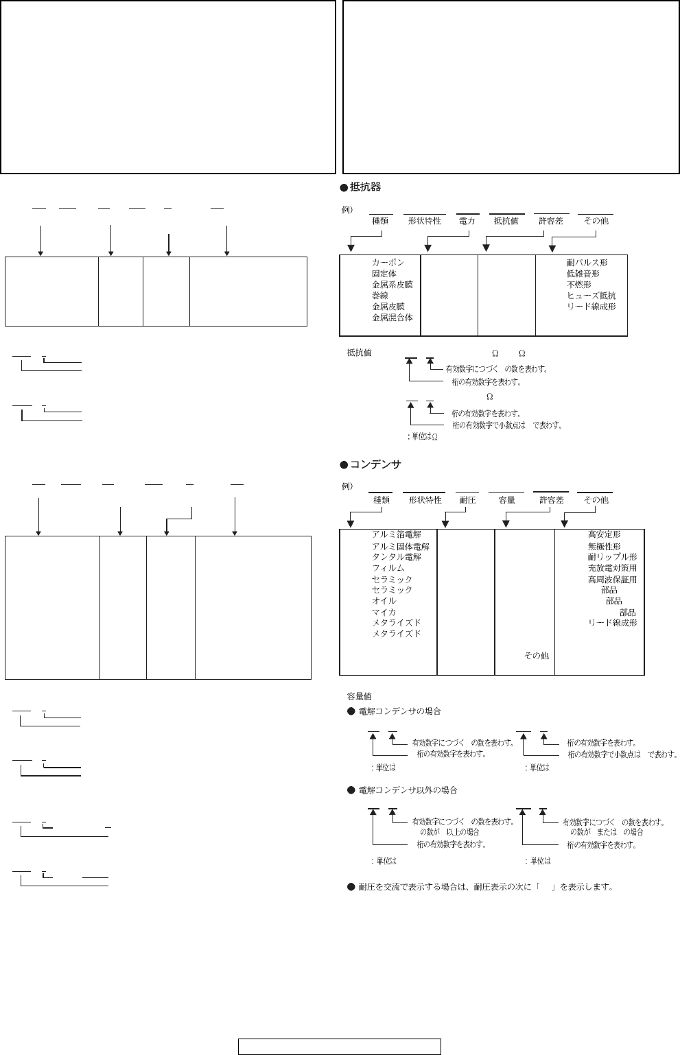
- NOTE FOR PARTS LIST 91
- PARTS LIST OF P.W.B. UNIT 92
- FRONT P.W.B. UNIT ASS'Y 99
- AVR-1909/789, AVC-1909 100
- INPUT P.W.B. UNIT ASS'Y 103
- POWER P.W.B. UNIT ASS'Y 106
- CPU P.W.B. UNIT ASS'Y 109
- HDMI P.W.B. UNIT ASS'Y 111
- VIDEO P.W.B. UNIT ASS'Y 119
- 2CH P.W.B. UNIT ASS'Y 123
- REG P.W.B. UNIT ASS'Y 125
- SIRIUS P.W.B. UNIT ASS'Y 126
- EXPLODED VIEW 127
- ---MEMO 128
- PARTS LIST OF EXPLODED VIEW 129
- PACKING VIEW 134
- NOTE FOR SCHEMATIC DIAGRAM 136
- SCHEMATIC DIAGRAMS (1/25) 137
- SCHEMATIC DIAGRAMS (2/25) 138
- SCHEMATIC DIAGRAMS (3/25) 139
- SCHEMATIC DIAGRAMS (4/25) 140
- SCHEMATIC DIAGRAMS (5/25) 141
- SCHEMATIC DIAGRAMS (6/25) 142
- SCHEMATIC DIAGRAMS (7/25) 143
- SCHEMATIC DIAGRAMS (8/25) 144
- SCHEMATIC DIAGRAMS (9/25) 145
- SCHEMATIC DIAGRAMS (10/25) 146
- SCHEMATIC DIAGRAMS (11/25) 147
- SCHEMATIC DIAGRAMS (12/25) 148
- SCHEMATIC DIAGRAMS (13/25) 149
- SCHEMATIC DIAGRAMS (14/25) 150
- SCHEMATIC DIAGRAMS (15/25) 151
- SCHEMATIC DIAGRAMS (16/25) 152
- SCHEMATIC DIAGRAMS (17/25) 153
- SCHEMATIC DIAGRAMS (18/25) 154
- SCHEMATIC DIAGRAMS (19/25) 155
- SCHEMATIC DIAGRAMS (20/25) 156
- SCHEMATIC DIAGRAMS (21/25) 157
- SCHEMATIC DIAGRAMS (22/25) 158
- SCHEMATIC DIAGRAMS (23/25) 159
- SCHEMATIC DIAGRAMS (24/25) 160
- SCHEMATIC DIAGRAMS (25/25) 161
© 2020, manymanuals.com. All rights reserved. | 0.157 s |
 Manymanuals.com
 Manymanuals.de
 Manymanuals.fr
 Manymanuals.it
 Manymanuals.pl
 Manymanuals.cz
 Manymanuals.es
 Manymanuals-pt.com
Comments to this Manuals