Denon AVR-1802/882 User Manual Page 10
- Page / 96
- Table of contents
- TROUBLESHOOTING
- BOOKMARKS
- AV SURROUND RECEIVER 1
- WARNING: 2
- ATTENTION 2
- SAFETY INSTRUCTIONS 3
- TABLE OF CONTENTS 4
- BEFORE USING 4
- 0.3 ft (10 cm) or more 5
- PART NAMES AND FUNCTIONS 6
- Remote control unit 7
- Step 3 (page 17 to 21) 8
- Step 2 (page 16) 8
- Step 1 (page 8 to 15) 8
- CONNECTIONS 9
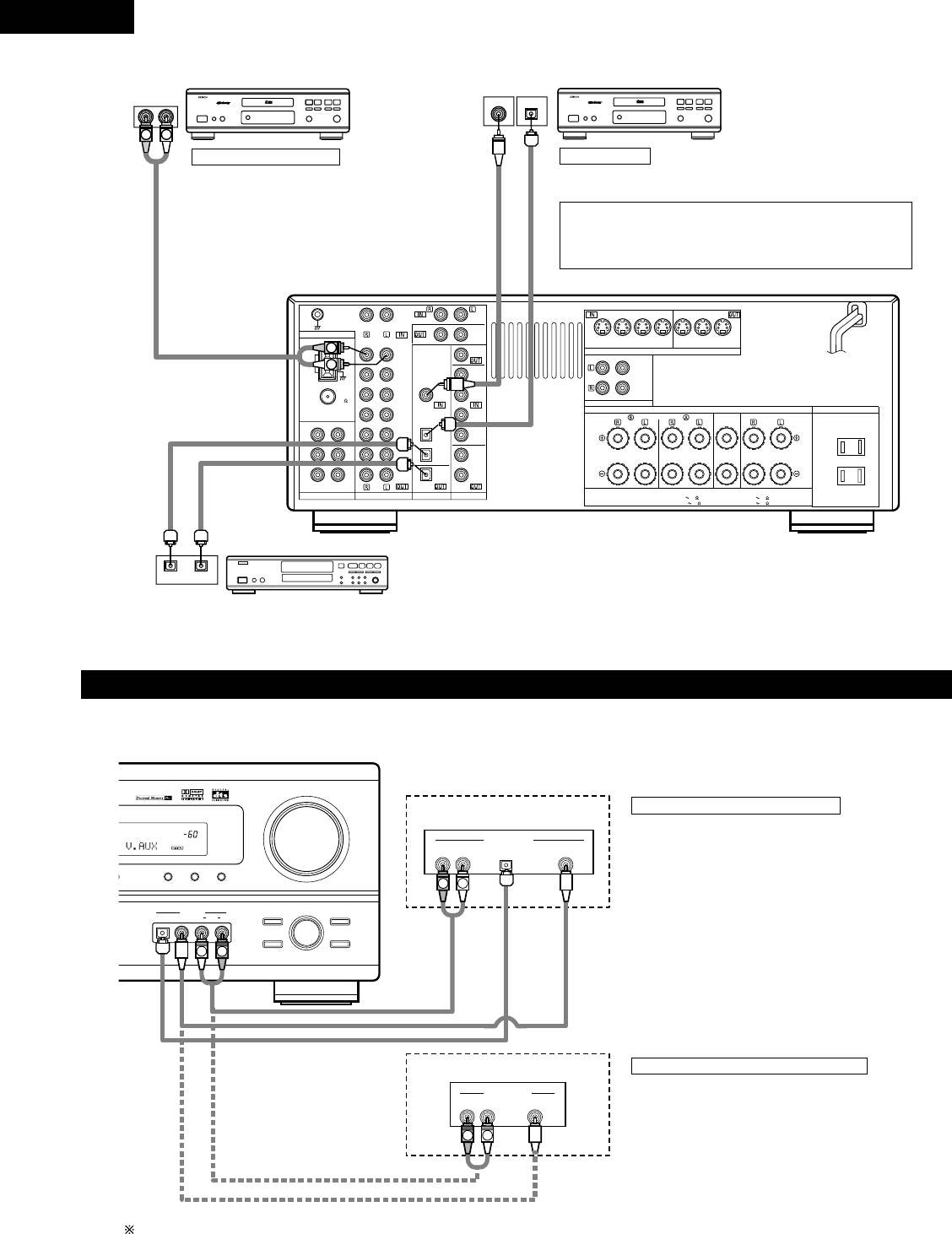
- Connecting a CD player 10
- DIGITAL jacks 10
- Connecting a TV/DBS tuner 11
- Connecting a video decks 11
- Connecting a monitor TV 12
- Connecting the video decks 12
- 3. Return the lever 13
- Speaker system connections 14
- Protector circuit 15
- Note on speaker impedance 15
- Inserting the batteries 16
- SETTING UP THE SYSTEM 17
- Before setting up the system 18
- Setting the SUBWOOFER MODE 19
- 6 FRNT/SW 12ft 20
- 7 CENTER 12ft 20
- 8 SURR. 10ft 20
- Digital input setup 21
- After setting up the system 21
- REMOTE CONTROL UNIT 22
- Before operating 25
- (Main unit) 25
- Playing the input source 26
- After starting playback 27
- (Remote control unit) 28
- Simultaneous recording 29
- SURROUND 30
- Dolby Surround Pro Logic 31
- II Mode: 32
- CINEMA EQ OFF 33
- D.COMP. OFF 34
- LFE 0dB 34
- DEFAULT Y/N 34
- DSP SURROUND SIMULATION 35
- ROOM SIZE MED 36
- EFFECT LEVEL 10 36
- Auto preset memory 40
- Auto tuning 41
- Manual tuning 41
- Preset stations 42
- Recalling preset stations 42
- LAST FUNCTION MEMORY 43
- ADDITIONAL INFORMATION 44
- DTS Digital Surround 46
- TROUBLESHOOTING 47
- SPECIFICATIONS 48
- TABLE DES MATIERES 49
- AVANT L‘UTILISATION 49
- 10 cm (0.3 pieds) ou plus 50
- NOMENCLATURE ET FONCTIONS 51
- FRANCAIS 52
- Etape 3 (page 62 à 66) 53
- Etape 2 (page 61) 53
- Etape 1 (page 53 à 60) 53
- CONNEXIONS 54
- Circuit de protection 60
- Insertion des piles 61
- INSTALLATION DU SYSTEME 62
- *SYSTEM SET UP 63
- 1 FRONT LARGE 63
- 2 CENTER SMALL 63
- 3 SURR. SMALL 63
- 4 S.WOOFER YES 64
- 5 SW MODE NORM 64
- 9 COAX DVD 66
- 10 OPT1 TV 66
- 11 OPT2 CDR 66
- UNITE DE TELECOMMANDE 67
- Avant l’utilisation 70
- (Unité principale) 70
- Après le début de la lecture 72
- (Unité principale) (Unité de 73
- AMBIANCE 75
- 2, 5, 74. 61 2 76
- 4, 5, 6, 7 76
- SIMULATION D’AMBIANCE DSP 80
- (Unité de télécommande) 82
- Mémoire préréglée automatique 85
- Syntonisation automatique 86
- Syntonisation manuelle 86
- Stations préréglée 87
- Rappel de stations préréglées 87
- MEMOIRE DE DERNIERE FONCTION 88
- INFORMATIONS SUPPLEMENTAIRES 89
- DEPISTAGE DES PANNES 92
- ENGLISH FRANCIAS 94
- ENGLISHFRANCIAS 95
- Telephone: (03) 3584-8111 96
Related products and manuals for Home Theater Systems Denon AVR-1802/882
 (2 pages)
 (90 pages)
© 2020, manymanuals.com. All rights reserved. | 2.461 s |
 Manymanuals.com
 Manymanuals.de
 Manymanuals.fr
 Manymanuals.it
 Manymanuals.pl
 Manymanuals.cz
 Manymanuals.es
 Manymanuals-pt.com
Comments to this Manuals