Denon AVR-5800 Operations Instructions
Browse online or download Operations Instructions for AV receivers Denon AVR-5800. Denon AVR-5800 Operating instructions User Manual
- Page / 112
- Table of contents
- TROUBLESHOOTING
- BOOKMARKS
- AVR-5800 1
- ATTENTION 2
- SAFETY INSTRUCTIONS 3
- TABLE OF CONTENTS 4
- BEFORE USING 4
- CAUTIONS ON INSTALLATION 4
- CAUTIONS ON HANDLING 5
- CONNECTIONS 6
- Connecting video components 7
- Connecting a monitor TV 8
- Connecting the video decks 8
- Connecting a TV/DBS tuner 8
- Jacks (DVD Player) 9
- Another room 11
- Protector circuit 12
- Note on speaker impedance 12
- Cooling fan 12
- Connections 13
- PART NAMES AND FUNCTIONS 14
- Remote control unit 15
- SETTING UP THE SYSTEM 16
- Before setting up the system 18
- ON / STANDBY 18
- (Main unit) 18
- Setting the type of speakers 19
- Setting the Subwoofer mode 20
- Setting the delay time 22
- Setting the channel level 25
- FL C FR SR SBR SBL SL SW 26
- Auto tuner presets 29
- After completing system setup 30
- REMOTE CONTROL UNIT 31
- Using the remote control unit 31
- OPERATION 32
- Playing the input source 33
- After starting playback 34
- SURROUND A SURROUND B 35
- SURROUND A+B 35
- 1, 41, 2 2 36
- EXT. IN-2EXT. IN-1 38
- Power amplifier (Option) 40
- INTEGRATED 41
- AMPLIFIER 41
- SURROUND 42
- FUNCTION 43
- THX CINEMA 45
- Dolby Surround Pro Logic mode 47
- DTS Neo:6 mode 47
- DENON ORIGINAL SURROUND MODES 48
- DSP surround simulation 49
- 2, 3, 4, 5 50
- LISTENING TO THE RADIO 52
- Preset memory 53
- Checking the preset stations 53
- LAST FUNCTION MEMORY 54
- ADDITIONAL INFORMATION 56
- Surround back speakers 57
- Speaker setting examples 58
- Surround 60
- DTS Digital Surround 61
- DTS-ES Extended Surround 62
- Home THX Cinema surround mode 63
- THX Surround EX 63
- Surround modes and parameters 65
- Telephone: (03) 3584-8111 67
- TABLE OF CONTENTS 69
- -, Phd-HIT&@ 74
- CHANNEI 76
- -.^ .. 78
- B)ENON ~~ 78
- - *““..“$ 78
- (ISP*CEI[Fj 83
- [-pi 83
- [Sl*IISlDEl[j 83
- Create New 90
- Backup Data? 90
- Cahbralion 90
- RF/IR Select 90
- User Menu 91
- User Backup 91
- ONE-BUTTON SEARCH FUNCTION 98
- RF TRANSMISSION FUNCTION 99
- FACTORY DEFAULT SETTINGS 99
- CAUTIONS ON USE 100
- TROUBLESHOOTING 100
- NIPPON COLUMBIA CO., LTD 101
- RC-8001 ST 102
- FEATURES 103
- BEFORE USING 103
- 3 NAMES OF PARTS 104
- RC-8000 105
- 5 OPERATION 106
- SPECIFICATIONS 107
- NIPPON COLUMBIA Co., LTD 108
- 511 3808000 109
- LIMITED WARRANTY 111
- DENON’ ELECTRONICS 112
Summary of Contents
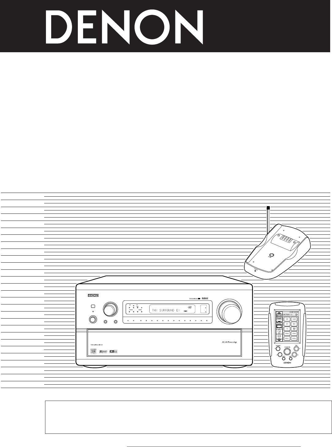
AV SURROUND RECEIVERAVR-5800OPERATING INSTRUCTIONSMASTER VOLUMEREMOTE SENSORON / STANDBYINPUT SELECTORHOMETHX CINEMAPURE DIRECTVOLUME LEVELAL24RFLOCKD
101423Connecting the antenna terminalsDIRECTION OF BROADCASTING STATIONAM LOOP ANTENNA(Supplied)FM ANTENNAGROUNDAM OUTDOORANTENNA300 Ω/ohmsTERMINALSFM
q CAUTIONS ON USE H Place of use Do not drop or subject to strong shocks. Dorng to could result rn damage. n Handling The touch pan
NIPPON COLUMBIA CO., LTD. 14-14, AKASAKA 4.CHOME, MINATO-KU, TOKYO 107-8011, JAPAN Telephone: (03) 3584-8111 Prmted in Japan 511 3672 00
CHARGER BASE STATION RC-8001 ST OPERATING INSTRUCTIONS MODE D’EMPLOI “SERIAL NO. PLEASE RECORD UNIT SERIAL NUMBER ATTACHED TO THE REAR
n We greatly appreciate your purchase of this unit. n To be sure you take maximum advantage of all the features this unit has to
cl 3 NAMES OF PARTS 0 Antenna @ DC IN terminal 0 Charging contacts @ EMITTER terminal 0 ENTER button 0 WIRED terminal 0 Charging indic
Use the procedure described below to connect the RC-8001 ST to a Denon device not equipped with a REMOTE IN terminal or to other dev
0 5 OPERATION RF transmission is possible when the RC-8001 ST is used in combination with the 1X-8000 (included with the AVR- 5800 or
When using the RF transmission function with multiple pairs of K-8000 and RC-8001ST, inadvertent operations could occur if the same R
NIPPON COLUMBIA Co., LTD. 14-14, AKASAKA 4-CHOME, MINATO-KU, TOKYO 107-8011, JAPAN Telephone: (03) 3584-8111 Printed in Japan 511 3687
Additional functions of the remote control unit (RC-8000) A newer software version has been installed on the remote control unit 6X
11Connecting the external input (EXT. IN) jacksConnecting the MULTI SOURCE jacks• These jacks are for inputting multi-channel audio signals from an ou
DENON SERVICE NETWORK/ flbi%~~ Please contact one of our overseas service centers, listed below, for follow-up service consultation. W
This warranty will be honored only in the U.S.A. DENON@ LIMITED WARRANTY Length of Warranty This warranty on your DENON audio product w
DENON’ ELECTRONICS, a Division of DENON Corporation (U.S.A.) Mailing address only: DENON ELECTRONICS, PO. Box 5370 Parsippany, N.J. 07054
12Speaker system connections• Connect the speaker terminals with the speakers making sure that likepolarities are matched ( < with < , > with
13Connections• When making connections, also refer to the operating instructions of the other components.SPEAKER SYSTEMSANTENNA TERMINALSMULTIZONESURR
146PART NAMES AND FUNCTIONSFront Panel• For details on the functions of these parts, refer to the pages given in parentheses ( ).qPower indicator...
15Remote control unit• For details, refer to the separate (supplied) RC-8000 operating instructions.The USB terminal is a terminal that will be used i
167SETTING UP THE SYSTEM• Once all connections with other AV components have been completed as described in “CONNECTIONS” (see pages 6 to 13), make th
17• Speaker system layoutBasic system layout (For a THX Surround EX system)• The following is an example of the basic layout for a system consisting o
18Before setting up the system1Check that all the connections arecorrect, then turn on the main unit’spower.2Either lightly press on the remote contro
19Setting the type of speakers• The composition of the signals output from the different channels and the frequency response are adjusted automaticall
22 SAFETY PRECAUTIONS2 NOTE ON USE / OBSERVATIONS RELATIVES A L’UTILISATION• Avoid high temperatures.Allow for sufficient heat dispersion wheninstalle
20• ParametersLarge ...Select this when using speakers that can fully reproduce low sounds of below 80 Hz. Small ...Select t
21NOTES:— Assignment of low frequency signal range —• The only signals produced from the subwoofer channel are LFE signals (during playback of Dolby D
22Setting the delay time• Input the distance between the listening position and the different speakers to set the delay time for the surround mode.• T
236Set the distance between thecenter speaker and listeningposition.The distance changes in units of 1foot (0.1 meters) each time thebutton is pressed
244Select the desired setting, then press jog stick “ENTER”.Variable:The level can be adjusted freely using the buttons on the remote control unit (M.
25Setting the channel level• Use this setting to adjust so that the playback level between the different channels is equal.• From the listening positi
267Select “Yes”.8a. If the “Auto” mode is selected: Test tones are automatically emitted from the different speakers.The test tones are emitted from t
27Subwoofer peak limit level setting• This unit features a subwoofer peak limit control which prevents distortion and damage in the loudspeaker system
28CAUTION!• The master volume is set to “–30 dB” when test tones are output.• The test tones are for confirming the low frequency playback limits and
29Setting the on-screen display (OSD)• Use this to turn the on-screen display (messages other than the menu screens) on or off.1At the System Setup Me
3SAFETY INSTRUCTIONS1. Read Instructions – All the safety and operatinginstructions should be read before the appliance isoperated.2. Retain Instructi
302Switch to the Auto Preset Memory screen.3Select “Yes” for Start.“Search” flashes on the screen and searching begins.“Completed” appears once search
318REMOTE CONTROL UNIT• The included remote control unit (RC-8000) can be used to operate not only the AVR-5800 but other remote control compatible DE
32Operating the remote control unit12Remote control unit’s jog stickLightly press “ENTER” to display the icons.Press the “ ” button on the icon displa
33Playing the input source213 51Select the input source to be played.INPUT SELECTOR(Main unit) (Remote control unit)Example: CDWhen the input source i
343Select the play mode.STEREO(Main unit) (Remote control unit)Example: Stereo4Start playback on the selected component.• For operating instructions,
353Adjust as desired with the CONTROL knob.• To increase the bass or treble: Turn the control clockwise. (The bass or treble sound can be increased to
36Multi-source recording/playback[1] Playing one source while recording another (REC OUT mode)1Press the REC/M-ZONE 2 button until“REC OUT SOURCE” app
37[3] Outputting a program source to an amplifier, etc., in a different room (M-ZONE 1 mode)1Press the M-ZONE 1 button.M-ZONE 12Select the source you
38Playback using the external input (EXT. IN) jacks1Set the external input (EXT. IN) mode.Press the EXT. IN (on the EXT. IN button on the remote contr
39Playing audio sources (CDs and DVDs)The AVR-5800 is equipped with three 2-channel playback modes exclusively for music.Select the mode to suit your
42 INTRODUCTION2 ACCESSORIESThank you for choosing the DENON AVR-5800 Digital Surround A / V receiver. This remarkable component has been engineered t
40Multi-source and multi-zone playbackMULTI ROOM MUSIC ENTERTAINMENT SYSTEM• When the outputs of the MULTI SOURCE AUDIO OUT terminals are wired and co
41[2] Multi-zone playback using the MULTI ZONE 2 terminalsThe AVR-5800 is equipped with audio pre output terminals with a fixed output level (M-ZONE 2
4210SURROUNDBefore playing with the surround function• Before playing with the surround function, be sure to use the test tones to adjust the playback
43Fader function• This function makes it possible to lower the volume of the front channels (FL, C and FR) or the rear channels (SL, SR, SBL and SBR)
44Playing modes for different sourcesThe AVR-5800 is equipped with many surround modes. We recommend using the surround modes as described below in o
45[1] Playing sources recorded in Dolby Pro Logic in the Home THX Cinema surround mode1Select the Home THX Cinema mode.HOMETHX CINEMA(Main unit) (Remo
46Dolby Digital mode (only with digital input) and DTS Surround (only with digital input)1Select the input source.INPUT SELECTOR(Main unit) (Remote co
47Surround parameters wCINEMA EQ. (Cinema Equalizer):The Cinema EQ function gently decreases the level of the extreme high frequencies, compensating f
4811DENON ORIGINAL SURROUND MODES• The AVR-5800 is equipped with a built-in high performance DSP (digital signal processor) that uses digital processi
49DSP surround simulation1Select the surround mode for the input channel.DIRECT STEREODOLBYSURROUNDDTSSURROUNDWIDESCREEN5CH / 7CHSTEREODSPSIMULATIONSU
53CAUTIONS ON HANDLING4FEATURES• Switching the input function when input jacks are notconnectedA clicking noise may be produced if the input function
50Tone control setting• Use the tone control setting to adjust the bass and treble as desired.1Display the surround parameterscreen on the monitor.The
51Surround parameters eEFFECT:This parameter turns the effect signals with multi surround mode speaker effects on and off in the WIDE SCREEN mode. Wh
5212LISTENING TO THE RADIOAuto tuning1Set the input function to “TUNER”.INPUT SELECTOR(Main unit) (Remote control unit)2Watching the display, press th
53Preset memory1Use the “Auto tuning” or “Manual tuning” operation to tunein the station to be preset in the memory.2Press the MEMORY button.3Main uni
54Recalling preset stations1Main unit:Watching the display, press the MODE SELECT button until“TUNER PRESET” appears on the set’s display.Remote contr
5515TROUBLESHOOTING If a problem should arise,first check the following.1. Are the connections correct ?2. Have you operated the receiver according to
5616ADDITIONAL INFORMATIONOptimum surround sound for different sourcesThere are currently various types of multi-channel signals (signals or formats w
57Surround back speakersThe THX Surround EX format adds new “Surround Back” (SB) channels to the conventional 5.1-channel system. This makes it easy
58• Set the front speakers, center speaker and subwoofer in the samepositions as in example (1).• It is best to place the surround speakers directly a
59• Set the front speakers slightly wider apart than the setup for watching movies only and point them toward the listeningposition in order assure cl
65CONNECTIONS• Do not plug in the AC cord until all connections have been completed.• Be sure to connect the left and right channels properly (left wi
60SurroundThe AVR-5800 is equipped with a digital signal processing circuit that lets you play program sources in the surround mode to achieve the sam
61(2) Dolby Pro LogicDolby Pro Logic is a multi-channel signal playback system developed by Dolby Laboratories which decodes sources recorded in Dolby
62DTS-ES Extended Surround TMDTS-ES Extended Surround is a new multi-channel digital signal format developed by Digital Theater Systems Inc. While of
63Home THX Cinema surround modeTHX is an exclusive set of standards and technologies established by the world-renowned film production company, Lucasf
64System setup items and default values (set upon shipment from the factory)System setup Default settingsqwtyuioSpeakerConfiguration(SurroundSpeakerSe
65Surround modes and parametersSignals and adjustability in the different modesChannel output Parameter (default values are shown in parentheses)When
6617SPECIFICATIONS 2 Audio section• Power amplifierRated output: Stereo (2ch driven) (All properties shown are only 170 W + 170 W (8 Ω/ohms, 20 Hz ~
14-14, AKASAKA 4-CHOME, MINATO-KU, TOKYO 107-8011, JAPANTelephone: (03) 3584-8111Printed in Japan 511 3624 006
REMOTE CONTROL UNIT RC-8000 OPERATING INSTRUCTIONS MODE D’EMPLOI FOR ENGLISH READERS PAGE 2 - PAGE 33 POUR LES LECTEURS FRANCAIS PAGE 34
n We greatly appreciate your purchase of this unit. 4 To be sure you take maximum advantage of all the features this unit has to
7Connecting video components• To connect the video signal, connect using a 75 Ω/ohms video signal cable cord. Using an improper cable can result in a
0 1 FEATURES The RC-8000 can be used for Integrated control of remote controllable devices connected to an AV amplifier (for example
0 3 NAMES OF PARTS - o f‘ @ Transmitter @ VOL. (volume) up/down buttons @ Touch panel @ LIGHT (back Irght) button @ CHANNEL up/down
[31 Adjusting the touch panel Adjust the touch panel so that keys on the touch panel can be operated with accuracy. Press “SETUP” r
Other operations When icon display section A is displayed, the device icons can also be scrolled by tiltrng the JOG stick forward
0 TAPE-2 Transmissron codes of independent buttons CHA : Tuner preset CHI : Tuner preset VOLA : Main volume of AV arnplrfrer VOLI : Main
n DENON DVD (DVD player and DVD changer) system buttons Transmission codes of Independent buttons VOLA : Main volume of AV amplifier V
n DENON CD (CD player and CD changer) system buttons Transmlsslon codes of independent buttons CHANNEI “0, 0 Q VOLA : Maln volume of A
W TAPE (tape deck) system buttons El nnn _“^ ,-xI-xII-xx .-_l.- _ U~l~~~~ ‘I’ t>i 000’ 000 000 000 000 The last page of the page display s
bevice icor 010 La I_y lo El iquipmeni AVAMP TUNER N DVD VCR MD DAT RCVR 3THER Manufacturer (codes) Device icon JVC (I to 5) MAGNAVOX (1 to 4)
111 Changing the preset memory of preset devices @I Touch the liquid crystal display to turn the display on. @ Press the JOG stick
8Connecting a video component equipped with S-Video jacks• When making connections, also refer to the operating instructions of the other components.•
121 Adding new devices a. b. c. d. a. f. Press the “SETUP” rcon rn the (con display sectron for at least 3 seconds to display the se
[31 Operating devices for which the preset memory is set For details, refer to the individual devrces’ operating instructions. % Note
n VCR (video cassette recorder) preset memory buttons n VCR (video cassette recorder) preset memory buttons lo lo 0 3 0 6 0 9 0 0 INPUT W
W CDR (CD recorder) preset memory buttons W VDP (video disc player) preset memory buttons e 1 OKeY W DES (satellite) preset memory b
W Cable (cable TV) preset memory buttons Ja 0 ENTER n LIGHT preset memory buttons Cl LOWER Transmissron codes of Independent buttons CHA
Devrces and buttons that cannot be operated using the preset memory (for which no preset signals are stored) can be operated by st
When learning is successful, “SUCCESS” is displayed. After this, the button name Input screen (“Key Label”) appears. Button name entry
The RC-8000 is equipped with a system call function for emitting a series of remote control signals by pressing a single button. Th
@ Press the - and - buttons rn the Icon display section to display the DVD icon, then press the DVD icon to select it. Here, pr
02 Deletrng buttons a. At the system call editing screen, press the button you want to delete so that it IS drsplayed In half- ton
9Connecting a Video Component Equipped with Color Difference (Component - Y, R-Y, B-Y) VideoJacks (DVD Player)• When making connections, also refer to
[II Backing up the current settings With the RC-8000, the current settings can be backed up. When you back up the settings, the se
141 Setting the back light’s auto off time With the K-8000, the back light automatically turns off if no buttons are pressed withi
0 5 OTHER REGISTERABLE DEVICES The devices shown below can also be registered. There is no preset memory for these additional devices
q Customizing (setting the operating environment) With the RC-8000. a total of up to 23 devrces to be operated can be registered. Up t
I31 Changing the positions of devices in the icon display section Use the procedure described below to change the order of the dev
141 Registering device names Use the procedure described below to register names, etc., for registered devices. @ Press “SETUP” in the
[ll Adding buttons “Learn” buttons to add them. Refer to section “Usrng the learning function” on page 18 121 Deleting buttons 0 Pre
I41 Use the Q and D buttons in the page display section to display the page containing the button you want to move, then press t
When “USER” is registered in the Icon drsplay section and the “User Menu” is set, the user screen (“CUSTOM l/2”) always appears when
@ Once the button is successfully learned, the preset memory search operation starts. Once the search operation is successfully comple
More documents for AV receivers Denon AVR-5800

Related products and manuals for AV receivers Denon AVR-5800
 (259 pages)
 (48 pages)
 (66 pages)
© 2020, manymanuals.com. All rights reserved. | 0.766 s |
 Manymanuals.com
 Manymanuals.de
 Manymanuals.fr
 Manymanuals.it
 Manymanuals.pl
 Manymanuals.cz
 Manymanuals.es
 Manymanuals-pt.com
Comments to this Manuals